
The Proxxon Pantograph
Disclaimer: I've never used a Proxxon Pantograph personally, so I can not vouch for the effectiveness of this system. Some people have been able to use the Proxxon Pantograph to successfully inlay shields into handles, and some people have had trouble. This article documents the methods that Steve Lund used, and what worked for him. Thanks -Chris
Precut Shields
I've heard from several knifemakes who have light weight pantographs such as the Proxxon or New Hermes, and one thing that they've mentioned is that they're able to cut pockets fine, but sometime they have a difficult time cutting stainless shields. Therefore, as a service, I've started cutting out shields that work with my templates. The shields are cut from .060" 410 stainless.
Can knife shields be cut with a Proxxon pantograph?
This is the question that Steve Lund has been trying to determine over the last few weeks. In a nutshell, the answer is yes... with a few modifications to the setup.
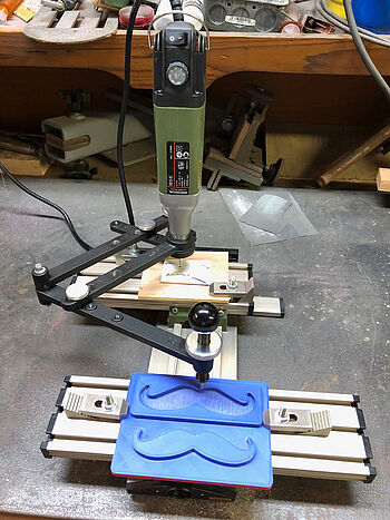
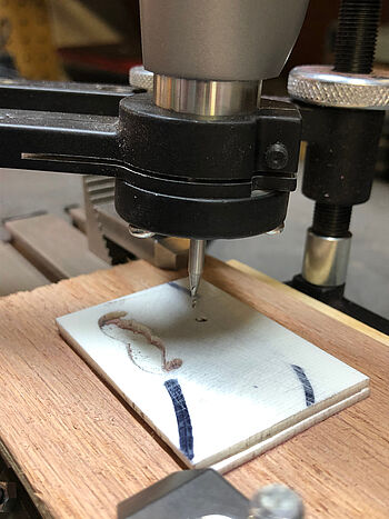
Steve and I had bounced some ideas back and forth concerning what may or may not work. After he got it all figured out, he sent me this picture:
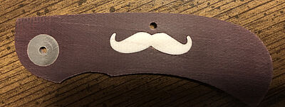
I asked Steve if he would mind writing up an article about it, that I could post on my website. Hopefully this page will help others who may have the same question.
So with that said, here's what Steve wrote...
What is a Pantograph and Why Do Knifemakers Want to Use Them?
According to Merriam-Webster’s online dictionary a pantograph is “an instrument for copying something (such as a map) on a predetermined scale consisting of four light rigid bars jointed in parallelogram form” (see the illustration below for an example). The use of a pantograph to trace and copy an original drawing occurred as early as the 1600s.
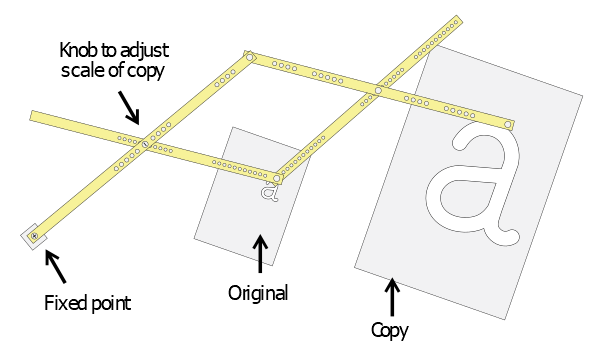
Knifemakers use pantographs for multiple purposes. Because you’ve come to Chris’ web site, read his pantograph pages and perhaps watched his video, you’re probably interested in using a pantograph milling machine to create and inlay shields in knife handle scales. Depending on the capabilities of the machine you wind up with, they can also be used to make simple or complex curves on bolsters and handle material so that they will fit together. Again, also depending on the machine, you might be able to cut pockets in integral knife frames as well as the handle material insert that fits into the inlay pockets.
Pantograph milling machines (pantograph mills) are used to make metal parts by tracing a pattern or template. Industrial models can reliably make small, intricate parts as well as very large heavy-duty parts. The first industrial pantograph that cut metal to duplicate machined parts was invented in the 1960s. One of the benefits of the pantograph is that the process it employs can make a duplicate part that is the same size, larger or smaller than the pattern being used. It is common to use a pantograph in reduction mode because any irregularity or imperfection in the pattern will be reduced by the reduction ratio to which the pantograph is set.
The concept of CNC (Computer Numerically Controlled) milling and CNC milling machines were conceived in the late 1940s. The first reliable production machines became available in the 1950s. Like all new technologies, they were very expensive in the beginning as well as difficult to learn to program and use. Over time, prices fell as the required technology became more common and as competition drove prices down. When technological advances and falling prices eventually made them more affordable, the CNC machine was preferred to the pantograph because it was far more accurate than a human, it could execute a preprogrammed set of instructions and to varying degrees, it could be used in an unattended manner. An operator could set up the machine by ensuring that the proper tools and raw materials were available, they were laid out where they were supposed to be (if the machine has the ability to change tools automatically) and then press the start button. The machine will take over and automatically produce some or all of the part.
Since pantographs were essentially replaced by CNC mills so long ago, today, it is getting harder and harder to find industrial pantographs. Especially if you want one in good condition, with all of the components and with a reasonably complete set of tooling. It doesn’t mean that you can’t find them, it just means that you’ll either have to pay a higher price to someone who has the expertise to restore them to useful condition or you might have to scrounge around to find the missing parts to rebuild one yourself. Assuming that you can find a pantograph in decent condition you can expect to spend anywhere from $1,000 - $3,000 for the machine, the spare parts you need to make it work again, and enough tooling to get started.
If you want to understand more of the details about how a pantograph works, you can find some useful information here:
Using the Proxxon Pantograph
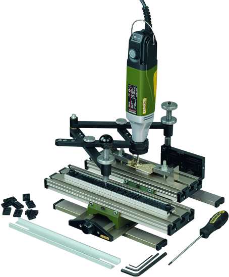
Billed by the maker as an engraving machine, the Proxxon GE20 must be used with Proxxon’s Professional Rotary Tool as the power tool that does the cutting. Other rotary tools (Dremel, etc.) don’t fit into the collar that secures the tool to the arms of the pantograph. So, at a minimum, you’ll have to buy the Proxxon pantograph and their rotary tool. I also recommend buying two of their clamp sets because they are the right size to be easily used with it (one set includes two clamps; you’ll need one pair for the copy table and another pair for the work table).
The GE20 includes a set of plastic lettering templates and a holder for them that fastens to the copy table by means of two clamps that fit into it (they are included with the machine). I have only used the engraving function of the machine once and wasn’t satisfied with the result but that is likely because I hadn’t practiced enough to get the hang of it and probably didn’t have the right nib for engraving. So, I can’t speak to its suitability for that purpose. At some point in the future, I will probably spend more time learning to engrave with it and perhaps offer additional information then.
The tip of the stylus that comes with the Proxxon pantograph that traces the pattern or template is cone shaped and is not the proper diameter to be a multiple of a 1/32” end mill (for example, if your pantograph is set for a 4:1 reduction, your stylus tip must be 4 times larger than the diameter of the end mill you intend to use). The size of the end mill is important because there may be a maximum size that will fit into the smallest areas of the pattern and accurately cut all the details of the template you are using.

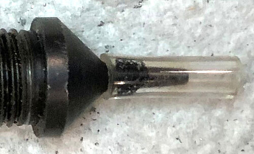
If you are using a 1/32” end mill (.03125”) then your stylus should be 4 times larger or 1/8” (.125”). In his video, Chris recommends using a .120” stylus with a 1/32” end mill. Using this diameter stylus results in a shield that is about .0006” smaller than if you used a .125” stylus and it causes the shield pocket to be cut about .0006” larger ensuring a very close but not overly tight fit (.0006” = .005” difference in the stylus diameter, divided in half because the radius of the end mill is the actual difference in the cut that is made, then divided by the reduction ratio of 4). This is a much better stylus/cutter choice especially when you are working to inlay a shield in a brittle or soft material (like mother of pearl or mammoth ivory, respectively) because you won’t have to apply much force to press the shield into the pocket.
So, I had to modify the stylus tip to get its diameter close to .125”. The first attempt at doing so was to buy a 1/8” brass tube, cut a small section to fit over the stylus tip with a jewelers saw, file the ends of the tube square and smooth, position it over the tip and fill the gap between the tube and the tip with superglue - ensuring that the tube was centered as well as possible. While this attempt worked as far as the stability of the tip was concerned, the fit of the resulting shield and pocket was too tight.
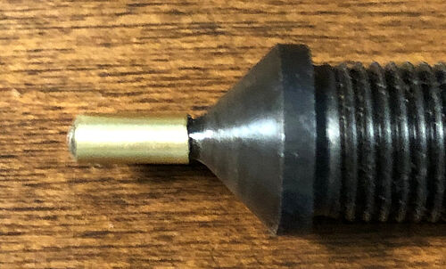
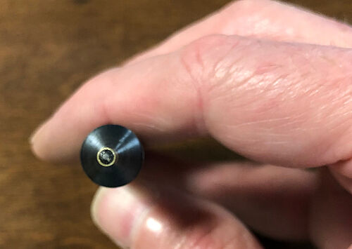
The stylus tip needed to be reduced to something around .120” as suggested in Chris’ video. I thought I could secure the stylus in my drill press chuck and while turning it, reduce it with either sandpaper or a file. If you decide to try this method, take care that you do not damage the threads on the stylus shaft.
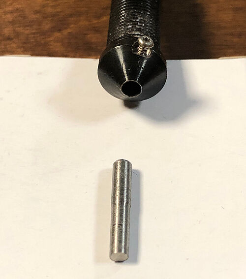
I also contacted a machinist who agreed to modify the stylus for me. Using a milling machine, he made a nylon block with a hole in it just large enough to press the stylus shaft into it but small enough for the fit to be snug. He put a nut on the stylus as close to the tip as it would go (the stylus has metric threads, M10 – 100, the nuts came from a Lowe’s Home Improvement Store), he milled a slot in the nylon block to fit and hold the nut securely by two of its sides, put another nut on the other end of the stylus and tightened it with a wrench until it was fairly tight. He could now hold the stylus, inside the nylon block, in his mill vise without damaging the threads on the stylus shaft.
At this point, he milled off the tip of the stylus, drilled a pilot hole in the exact center of the stylus (using a dial indicator to locate the center) and then enlarged the pilot hole in the stylus tip by drilling it with a 1/8” drill bit. The next step was to mill a tiny flat on the side of the stylus (so that he wasn’t drilling a set screw hole into the cone shaped head of the stylus (above the tip) but rather into a flat spot so that the drill bit wouldn’t wander.
Again, as before, he started the hole with a center drill and then drilled the set screw hole of the appropriate size to be tapped for a 0 – 80 screw. The hole was tapped and a screw turned into it.
He went to his lathe and turned several short lengths of stainless rod to an 1/8” shank and turned the tips to several different diameters. The dimension of the first tip he turned was approximately .001” to .002” smaller than the original .125” shank. He also made four more tips reducing each one by another .001” or .002”. I found that the .119” tip worked the best with the templates I bought from Chris.

List of Materials & Prices
- Carbide Tool Source: 1/32” Carbide Ball End Mills – 10 for $37.50 with free shipping
- Proxxon Engraving Device GE20: $256.25
- Proxxon 38481 Professional Rotary Tool: $108.34
- Proxxon 24256 Step Clamp Set (Recommend 2 Pairs): $55.00 ($27.50 per pair)
- Wiha 26430 Precision Screwdriver Ball End Hex Metric 3.0 X 60mm: $10.67
You can expect to spend around $500, including a few of Chris’ templates.
If you take the route of having a machinist modify your stylus, the cost of machining is not included in the figure above. If you go with the brass tube method, the tube was purchased at Ace Hardware. A 12” long, 1/8” tube was under $2.00.
(Prices are accurate as of September 2020)
Set-Up Considerations
One of the differences between the Proxxon and a full-size pantograph is the size of the work table. The Proxxon’s work table measures approximately 2.75” X 8.375”. Because you need to leave some room for clamping the work to the table, there is a practical limit to the size of the raw material from which you can cut your shield or cut a pocket for a shield to be inserted. You shouldn’t have a problem with the size of the handle material for most folders. However, you won’t be able to use a sandwich of steel and micarta the size that Chris does in his video because the Proxxon won’t hold a plate that large. I have made steel and wood “sandwiches” for the Proxxon from which you can easily cut four or five shields.
If you are cutting steel or another metal, I have been successful following Chris’ advice from his video. A plate of steel can be glued to a micarta or wood base and the base can be clamped to the work table. When the material being cut isn’t metal, you may not be able to remove it from the base using a torch to soften the glue because it would burn the shield material. In that case, double-sided carpet tape has worked well for me. I’ve affixed the non-metallic material to a thin wooden base with tape. I don’t recommend using tape with metal because as the metal gets warm from machining, the tape may loosen and the part can move causing your work to be ruined (ask me how I know that!). One undesirable side effect of using tape is that the adhesive sticks to and bunches up on the end mill as you begin to cut through the bottom of the material from which you are making the shield. You may have to remove the end mill from the work, turn off the rotary tool and clean the adhesive off of the tip before making your final passes.
The instruction manual that comes with the Proxxon Pantograph is woefully inadequate. There are less than three pages of instructions in English. So, here are some tips that will get you started, and hopefully help you avoid some of the pitfalls that I suffered through in my trial and error approach.
The arms of the pantograph (and thus the stylus and cutter) are moved up and down by means of two threaded shafts. One of them is the stylus itself and the other is located at the back of the machine. There is a knurled locknut on both shafts. The arms of the pantograph are raised and lowered by loosening the locknut, turning the shaft(s) and locking them by turning the locknut tightly against the arms. I have had the best results by following these steps:
- With the cutting tool and pantograph arms swiveled out of the way, place the material to be cut on the work table with the clamps loosely in place.
- Put the template or pattern on the copy table as you did the material above on the work table but do not tighten the clamps yet.
- You will have to move the tables, template and raw material to adjust the point where the end mill will cut on the material. At a 4:1 reduction ratio, there is about 4” between the tables (plus or minus the location on the tables where you affix the template and the material to be cut). Instructions on adjusting the tables can be found on Page 10 of the manual included with the pantograph.
- When the template and material to be cut have been adjusted and clamped securely to their tables, make sure that the arms have been adjusted high enough so that when you swivel the cutter back over the material, it doesn’t make contact and either break the end mill or scratch the material.
- With the stylus hovering over the template, using the threaded shaft at the rear of the machine, adjust the height of the cutter until it is almost touching the surface of the material that is being cut.
- Loosen the locknut on the stylus and turn it until the arms of the pantograph are level and the tip of the stylus is lightly resting on the template (the end mill should not be touching the material yet). This ensures that the cut you will make in the material will be perpendicular with the surface of the material and not at an angle. Tighten the stylus locknut. If you’re cutting thin material or a shallow pocket (.060” or less) you shouldn’t have to readjust the stylus height.
- The pantograph arm assembly is spring loaded at the back of the machine. It can be tilted up and down by raising or lowering the stylus.
- With the stylus raised from the template so that the end mill will not touch the material being cut, switch the rotary tool on, adjust it to full speed, loosen the locknut on the rear threaded shaft, lower the cutter and tighten the locknut (read the next three steps carefully and make sure you understand them before attempting your first cut).
- If you are cutting metal (stainless, brass, etc.), turn the knob on the rear threaded shaft approximately 1/8 turn counterclockwise to move the cutter down towards the material being cut, make one pass around/across/through the pattern and raise the cutter out of the work by lifting the stylus.
If cutting a softer material, like micarta, the cutter can be lowered around ¼ turn per pass. (Remember, the material and/or the “sandwich” you are cutting may not present a perfectly flat surface to the end mill. So, approach the surface very slowly and dial the cutter lower and lower ever so slightly at first, until you make contact with the surface. Be sure to make one complete revolution around the entire template before each lowering of the stylus because you may initially make contact at some point(s) on the surface before other points and you don’t want to make a cut that is too deep and break an end mill). - If you are cutting out a shield, continue making successive, deeper passes through the material until you break through the base to which the material is glued or taped. Be sure that you have broken through the material being cut all the way around the outline of the shield before you stop cutting and remove the “sandwich” from the work table. The idea here is to make sure that there is no “chad” hanging off of the shield because it will be difficult or impossible to accurately remove it without changing the shape of the shield (ask me how I know this as well). If you’re using a micarta base, for example, make sure that the end mill is cutting all the way through the shield material and well into the micarta all the way around the circumference of the shield before you stop making cutting passes or move the work.
- If you are cutting the pocket for a shield, continue making successive, deeper passes into the material being cut until the pocket is the desired depth. Remember, during each pass, you have to cut away all of the material inside the pocket; this is sort of like coloring inside the lines and making sure that you have cut out the entire area inside the pocket.
- Be sure that you raise the cutter and hold it up out of the material being cut while you adjust the rear threaded shaft to increase the cutting depth for each successive pass.
- When cutting a shield, also be careful when you lower the cutter back into the material, that you enter the material well outside of the shield template because you don’t want to cut into the surface of the shield.
- Likewise, when cutting a pocket, be careful when you lower the cutter back into the material, that you enter the material well inside the pocket so that you don’t unintentionally cut into the handle material outside of where the pocket is located. This could be a real disaster if an undesired cut is made into expensive handle material.
Pros & Cons
Pros:
- Brand new machine
- Relatively low cost as compared to industrial models (if you can even find an industrial pantograph complete and in good shape)
- Compact (requires way less space than an industrial model)
- Tabletop, light weight, easily moved around
- Incredibly easy to set up the reduction ratio (predrilled and tapped holes in the pantograph arms, set with thumbscrews)
- Works great with Chris’ pantograph templates (be careful not to overtighten the template when you clamp it to the copy table, it’s light plastic and can crack)
Cons:
- Lightweight machine, not robust enough to mill large parts
- Thumbscrews that are used to set the reduction ratio can come loose after a pass or two – they must be checked frequently to ensure that they stay tight. If the thumbscrews loosen, the rotary tool can jump around resulting in a broken end mill and/or a divot carved into the edges of the cut. This isn’t a big deal; you just need to check/retighten them every other pass around the template – only takes a second or two.
- The Proxxon instruction manual leaves much to the imagination and isn’t a complete guide on how to use the machine as a mill to cut out parts.
Manufacturers of Industrial Milling Machines
If you want to search the internet for information on full size, industrial mills, here is a list of some of the manufacturers. I’m sure that there are many other makers. These seem to be the most common.
- Alexander
- Deckel
- Gorton (P1 – 2 is the model Chris has)
- Manek
- Pear
- Sakazaki
- Scripta (France, there was a Scripta company in the US but they were the US distributor for Scripta)
Summary
In all my research, over months of time, I could not find another small, tabletop pantograph similar to the Proxxon. It is really well made and I heartily recommend it if you don’t think you’ll ever be interested in a full-size pantograph or if you’re on a tight budget and want to start out with an entry level machine of good quality. Proxxon makes excellent tools and tooling. However, you can get high quality tooling (end mills, engraving nibs, etc.) from other sources at much better prices.
I’m happy with the Proxxon and don’t have any current plans to move up to an industrial pantograph mill. In addition, I’m out of room in my shop and don’t have space for a bigger machine.
You might want to consider ordering from Amazon because you can get all of the items you need on one order from one place (except the 1/32” end mills; Chris recommends Carbide Tool Source). And, on an order of this amount, you’ll probably get free shipping from Amazon.
Even though the pantograph comes with all the hex wrenches you’ll need, it’s handy to have a longer, straight, 3.00mm hex screwdriver to loosen and tighten the clamp that holds the rotary tool in its socket. If you don’t already have one, consider this one from Amazon: Wiha 26430 Precision Screwdriver Ball End Hex Metric 3.0 X 60mm. It’s around $11.00.
The pantograph comes with a screwdriver style hex wrench that is used to loosen and tighten the copy and work tables. Both tables move from side to side and from front to back.
The pantograph drawing was created by Inigolv, and is used under the Creative Commons Attribution license. The picture of the Proxxon pantograph was taken from proxxon.com, where the pantograph can be purchased. All other pictures were taken and supplied by Steve Lund.


